The relationship between waterproof connectors and cables
 2024.05.13
 Industry news
Most people think that waterproof connectors have little to do with cables. It's hard to say. It depends on the situation. Different products, including metal fixed heads, etc. are used depending on the situation. When we install a cable, we often have to consider its lifespan. How to ensure its service life is very important. Because the cable is directly exposed, it is particularly important that the outer layer must be protected by something. Based on our experience, we will analyze what may be available, but it is not a technical article and is for reference only. First of all, the cables are composed of several or more wires. Finally, the first wire is surrounded by more than one circle of insulating tape. Then use professional mica tape to surround it in two layers to ensure its compactness.
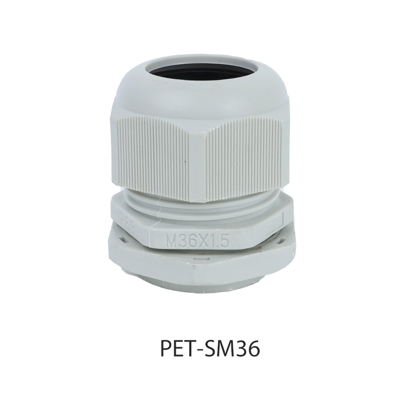
Install the cable waterproof connector and wrap it with more than two layers of tape to ensure that the bundle is strong. It is more environmentally friendly to use epoxy resin or other surface treatment. Make sure it is completely dry before use. Finally, wrap a heat shrink tube around the outer layer of the exposed road and that's it.
What Are the Advantages of Hose Waterproof Connectors?
In the demanding environments of industrial automation, marine applications, and outdoor machinery, ensuring a reliable electrical connection is paramount. This is where hose waterproof connectors, often referred to as heavy-duty connectors or cable connectors, prove indispensable. Their design goes far beyond a simple plug and socket, offering a robust solution for power, signal, and data transmission in the harshest conditions. But what specific advantages make them a preferred choice for engineers and system integrators?
The primary benefit is, unsurprisingly, exceptional ingress protection. These connectors are engineered to meet high IP (Ingress Protection) ratings, such as IP67, IP68, and IP69K. This means they are completely dust-tight and can withstand prolonged immersion in water under significant pressure. This level of protection safeguards internal components from moisture, dust, oils, and chemicals, drastically reducing the risk of short circuits, corrosion, and ultimately, system failure.
Beyond mere waterproofing, their robust construction offers mechanical strength. Manufactured from high-quality materials like thermoplastics, stainless steel, or brass, they are built to resist impact, vibration, and mechanical stress that would destroy standard connectors. This durability ensures a longer service life and reduces maintenance costs and downtime. Furthermore, their modular design is a significant advantage. Many systems allow for the integration of various inserts within a single shell, accommodating power, coaxial, data, and pneumatic lines. This simplifies cabinet design, reduces part numbers, and streamlines both installation and future modifications. The plug-and-play nature also means that cabling can be pre-assembled and tested off-site, dramatically speeding up on-site installation and commissioning. In essence, hose waterproof connectors provide a holistic solution that enhances system reliability, safety, and operational efficiency.
What Are the Styles of Junction Box Cable Connectors?
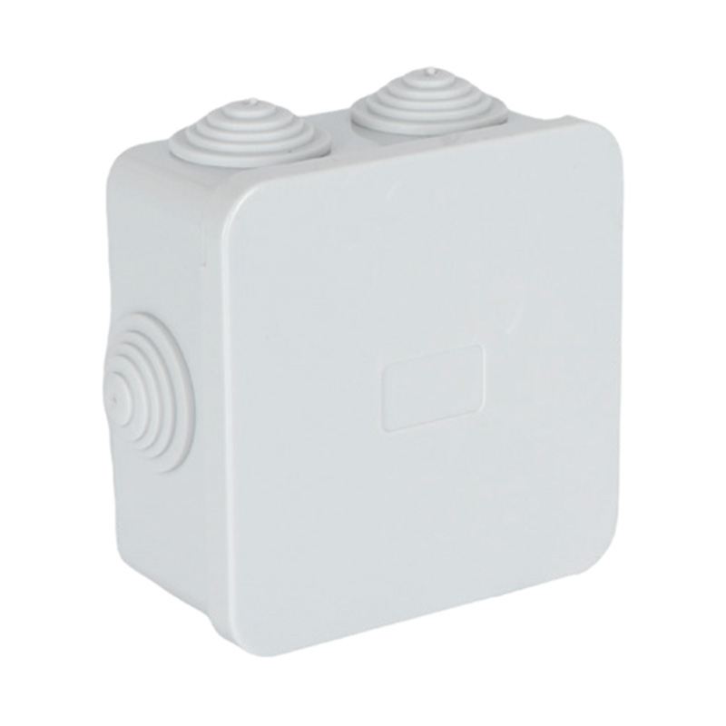
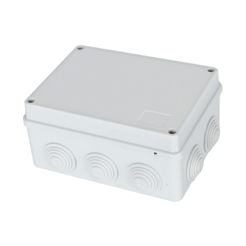
Junction boxes are the critical nodal points in any electrical system, where circuits are connected and protected. The integrity of these boxes relies heavily on the cable connectors, or glands, used to secure and seal the entry points of wires and cables. Selecting the right style is crucial for safety, functionality, and compliance. So, what are the common styles of junction box cable connectors available?
The ubiquitous style is the compression gland. Recognizable by its nut and olive (ferrule) design, this type is used for creating a tight seal around a cable. As the nut is tightened, it compresses the olive onto the cable sheath, providing a strong grip and a environmental seal, typically rated to IP66 or IP68. They are versatile and come in various materials like nylon for general use or brass and stainless steel for more corrosive or hazardous environments.
For applications requiring frequent changes or additions to wiring, multi-hole cable glands or blanking plugs are essential. Instead of a dedicated gland for each cable, a larger entry point is fitted with a modular gland that has multiple smaller holes or inserts. This allows for a more adaptable and cleaner installation, simplifying the process of adding or removing cables without needing to drill new holes in the enclosure.
The electrical cable gland, a seemingly simple component, has a history that parallels the evolution of electrical engineering itself. Its development is a story of responding to the growing demands for safety, reliability, and standardization as electricity moved from laboratory curiosity to industrial and domestic ubiquity. How did this critical component come to be?
In the earliest days of electrical distribution during the late 19th and early 20th centuries, installations were rudimentary and often dangerous. Cables were frequently fed through holes in wooden boards or metal enclosures, with perhaps a rudimentary grommet to prevent abrasion. There was little thought given to environmental sealing or strain relief, frequent failures, short circuits, and fires. The need for a safer, more reliable method of cable termination became acutely apparent as electrical systems spread into factories, mines, and ships—environments filled with moisture, dust, and flammable materials.
The initial innovations were likely born in these heavy industries. The patented cable glands emerged in the early 20th century, designed primarily to provide a basic mechanical grip and a measure of sealing. These early designs were often made of machined brass and used a simple compression principle. The two World Wars acted as a significant catalyst for their development. The military, particularly the naval sector, required electrical systems that could withstand conditions on warships and submarines. This drove the creation of glands that could provide a truly watertight and pressure-resistant seal, the formalization of performance standards.


 English
 中文简体
中文简体 Español
 عربى
عربى

